Visibility-based Analysis Zones
A unique feature of Analysis Zones is that they can be drawn and placed according to 'visibility'. This means that, from a chosen viewpoint (a single point or a defined segment), the shape and extent of an Analysis Zone can be calculated and placed according to how visible an area of your model is from the chosen viewpoint.
This method limits the shape and size of the finished zone by viewing distance and viewing angles: it stands to reason that physical objects can only be viewed within a certain distance and between certain angles. This drawing method produces a shape, which reflects these physical and optical limitations.
This is useful when you want to analyse the impact of signs, information boards, or advertisements within a site, while taking obstacles and interruptions to sight lines into consideration. An Analysis Zone can be placed that covers just the area in which Entities can view a certain element of the venue, thus honing in on its effectiveness as a source of information and influencer of movement.
To draw a visibility-based Analysis Zone for a point:
-
Click the visibility drawing icon
 (any icons and features not
connected with visibility drawing are disabled).
(any icons and features not
connected with visibility drawing are disabled).
-
Click the Analysis Zone icon
 .
.
You are prompted to select "Visibility for Point or Segment? [P]/S"
- For a point, hit Return.
-
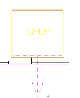
Click to place the visibility point. Choose the point whose
visibility you want the Analysis Zone to calculate and model. This should be
the centre of the object (camera, small sign, etc.). Use the pan and zoom tools
as normal if required.
Note: You can only place your point inside the model's accessible space. A dotted line is temporarily imposed on the model, delineating areas of accessible space.
You are prompted to "Move mouse to change distance".
-
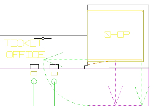
To set the distance from where you wish to calculate the
visibility of the point, move the mouse to the required place and left-click to
fix it. By dragging the visibility arrow, you can affect distance and
direction. You can also type the distance coordinates (two figures are needed)
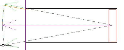
directly into the Command bar if you prefer. This screen shot shows the point
in the middle of a street Exit. The arrow has been extended to the required
visibility distance.
You can now set the low and high angles from which your point can be seen.
- To set the low angle, move your mouse to the required position and left-click.
- To set the opposite (high) angle, move your mouse to the required position and left-click.
-
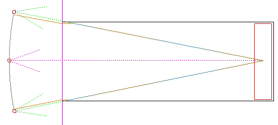
You can now review your settings and, if you need to make any
adjustments, you can 'grab' the various distance and angle markers by clicking
on them and moving them. They are highlighted in red, as in this screen shot.
When you're happy with the shape of the Analysis Zone, hit Return. The ‘Edit Analysis Zone’ dialog box is displayed.
-
Enter an appropriate name for the Analysis Zone and click
OK.
The new zone appears in the workspace and in the Object Directory, in the Analysis Layer.
-
Repeat from step 2 for any more Visibility-based Analysis Zones
you would like to place. To exit 'visibility mode', click the
icon again.

To draw a visibility-based Analysis Zone for a segment:
-
Click the visibility drawing icon
.
-
Click the Analysis Zone icon
.
You are prompted to select "Visibility for Point or Segment? [P]/S"
- For segment, type s and hit Return.
-
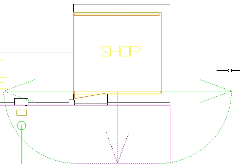
Draw the segment as you would draw a line of CAD or the side of
any object. Use the pan and zoom tools as normal if required. These screen
shots illustrate the use of a segment across a visible shopfront.
Tip: Drawing from left to right will create a directional arrow pointing up; drawing from right to left will create a directional arrow pointing down; drawing top to bottom will create a directional arrow pointing to the right; drawing bottom to top will create a directional arrow pointing to the left. Also, you can only draw your segment inside the model's accessible space. A dotted line is temporarily imposed on the model, delineating areas of accessible space.
You are prompted to "Move mouse to change distance".
-
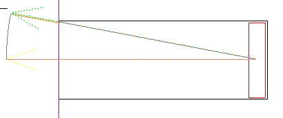
To set the distance from where you wish to calculate the
visibility of the segment, move the mouse to the required place and left-click
to fix it. By dragging the visibility arrow, you can affect distance and
direction. You can also type the distance coordinates (two figures are needed)
directly into the Command bar if you prefer. This screen shot shows the segment
drawn along one side of a retail unit. The arrow has been extended to the
required visibility distance.
You can now set the low and high angles from which your segment can be seen.
- To set the low angle, move your mouse to the required position and left-click.
- To set the opposite (high) angle, move your mouse to the required position and left-click.
-
You can now review your settings and, if you need to make any
adjustments, you can 'grab' the various distance and angle markers by clicking
on them and moving them. They are highlighted in red, as in this screen shot.
When you're happy with the shape of the Analysis Zone, hit Return. The ‘Edit Analysis Zone’ dialog box is displayed.
-
Enter an appropriate name for the Analysis Zone and click
OK.
The new zone appears in the workspace and in the Object Directory, in the Analysis Layer.
-
Repeat from step 2 for any more Visibility-based Analysis Zones
you would like to place. To exit 'visibility mode', click the
icon again.